
The vast majority of recordings are produced by sound engineers in such a way that sound sources are correctly positioned in space when played via speakers in a dedicated listening room (a room with low levels of reflections).
When playing music via acoustic systems, the sound signal from the left speaker enters the left ear and passing by the listener's head also enters the right ear (which results in a delay and change in amplitude/phase response), the same occurs with the sound signal from the right speaker, as shown in Figure 1a. The listening via acoustic speaker systems is affected by the following main problems: the huge effect of the listening room and the lack of pointed radiation of sound. For headphone listening, however, the radiation from the left earphone is fed only to the left ear and the radiation from the right earphone is fed only to the right ear (see Fig.1b). Therefore, despite the fact that headphones are not affected by the problems related to the acoustic systems, because of the improper localization of the sound sources ("in head localization phenomenon", see Fig. 3), the headphones are not suitable for high-quality reproduction of music or mixing phonograms at the studio.
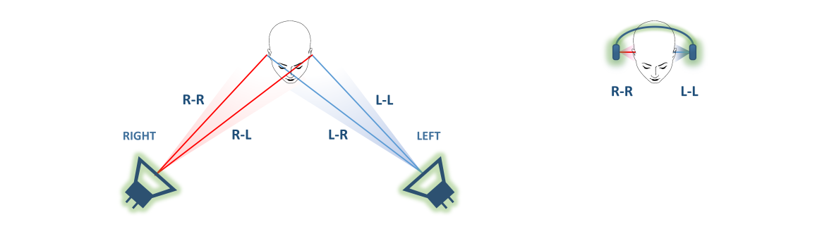
Figure 1 a/b
To get the correct localization of sound sources when listening to music via headphones, you need to use the electrical equivalent of the physical processes that occur when listening via the speakers — a binaural audio processor, also known as cross-feed.
Most of the headphone amplifiers with cross-feed feature (RME ADI-2, SPL Phonitor, Meier audio, Grace m902 / m903 / m920, HeadRoom Ultra Desktop Amp, Headstage Arrow, etc.) are based on passive 2–4th order filters — their frequency/phase response are far from optimal (at 10 kHz, the phase-frequency variation is <- 70 degrees while more than -1,600 degrees are required, not optimal frequency response) [4-6, 15-18, 24-31], which in turn explains the ambiguous subjective results when using headphones with such cross-feed processor, because the already poor localization of the sound sources becomes even weirder. The existing software implementations [21][22] completely repeat their hardware counterparts in terms of amplitude/phase response and, therefore, are also not recommended for high-quality listening of music via headphones.
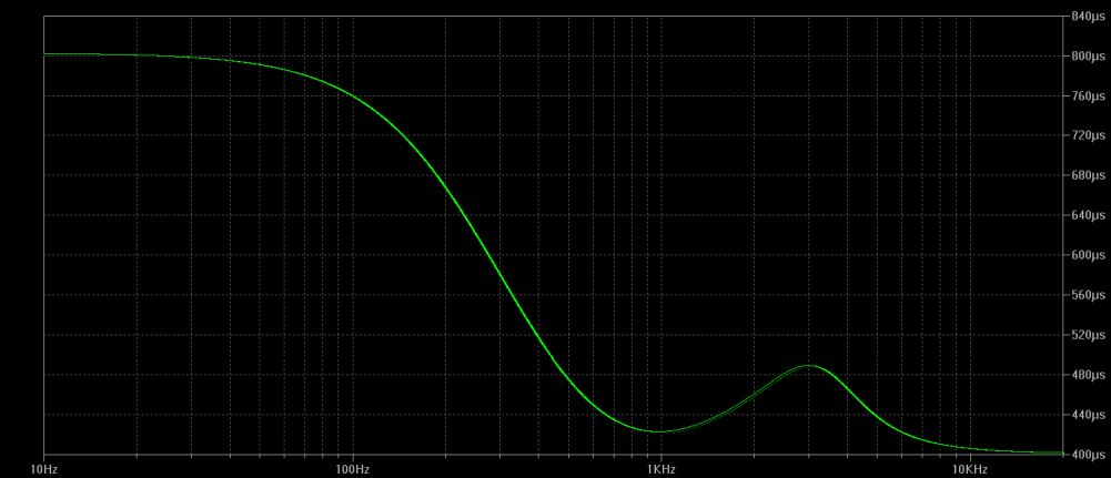
Figure 2
Thus, after many years of development, a binaural audio processor was created, that ensures compliance with the real physical processes with good accuracy, namely, emulation of speakers located in an open space at the angle of +-45 degrees in front of a listener. Figure 2 shows a graph of the delay of a signal mixed by a binaural processor in the L (R) channel, corresponding to the location of the speakers at the angle of + -45 degrees. The use of such a complex binaural audio processor allows to emulate the sound of the near-field speakers in the open space with good azimuthal localization of sound sources when listening to headphones (see Fig. 3)
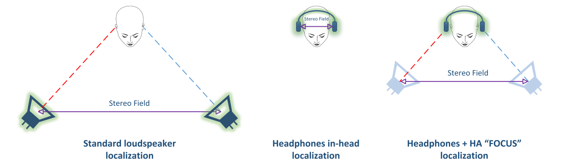
Figure 3
The block diagram of the "Focus" headphone amplifier is shown in Figure 4. The device has USB input using the CM6631A chip in asynchronous mode with custom-made firmware written in C programming language. The low-jitter oscillator from Epson is used as a clock for the CM6631A.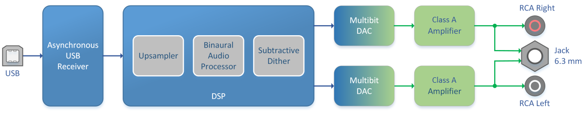
Figure 4
Unlike standard schematics, where the DSP is necessarily used with asynchronous sample rate conversion(ASRC), the DSP is used in a non-standard way, so there is no need for the ASRC, which eliminates the inevitable deterioration of sound quality due to its use.
The upsampler converts the 44.1 kHz sampling rate audio to high resolution format using the unique custom digital filter:
- Passband up to 22 kHz
- Stopband from 22.5 kHz
- Stopband attenuation is 81 dB
- no passband ripple
The minor aliases are additionally delayed for a few milliseconds, which allows them to be masked due to the Haas effect. . Thus, we get a filter with the maximum possible bandwidth and no aliasing-related problems.
For 44.1 kHz sampling rate, different digital filters can radically change the sound of the device, due to the fact that the sampling frequency is chosen too tight, because an ear needs a sound reproducing band slightly larger than the 20 kHz, which leads to a tough struggle to find a balance between computing resources, passband and aliases. Or some marketing factors come into play, and the digital filter is intentionally made to produce “distorted” sound which is recognizable and not similar to other brands.
The digital filter (Figure 5) used in this device allows the listener to re-discover records with the 44.1 kHz sampling rate. Now the sound recorded with the classic 44.1 kHz sampling rate sounds as good as high-res recordings. When downsampling hi-res recordings to 44.1 kHz, it is very difficult to tell what is being playing at the moment, recording in an old 44.1 kHz sampling rate or hi-res recording.
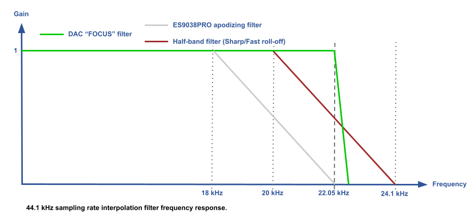
Figure 5
For 88.2–192 kHz sampling frequencies the minimal phase apodizing FIR digital filter [42][43] is used. Unlike the half-band digital filters typical for all DACs, this type of filter fulfills the requirements of the Nyquist–Shannon sampling theorem, namely, it completely eliminates aliases (free from spectral overlap), thereby reliably restoring the audio signal.
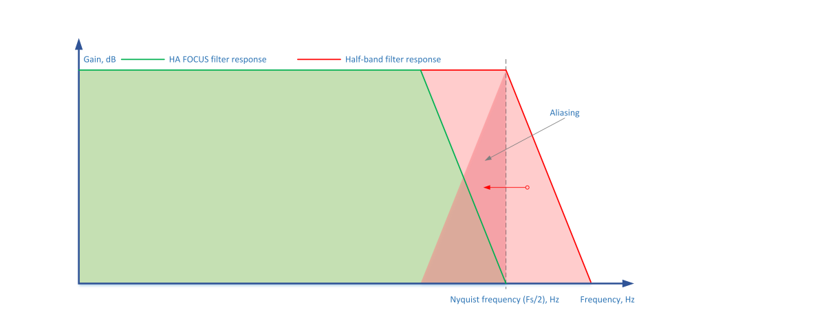
Introduction of the apodizing filter into the playback chain does not remove any audio information, instead the filter removes pre-ringing and post-ringing of all half-band DFs, both the ones used during the music recording (!) and the ones used inside the DAC chip, while preserving the integrity of the original audio. All that remains is the postringing of this filter (Figure 6), which is effectively masked by the useful signal.
Mathematical calculations with 24-bit input data are performed with 28/56-bit coefficients using a 56-bit accumulator.
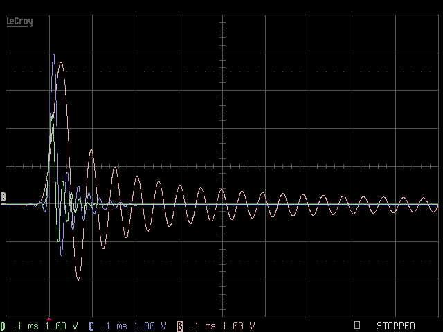
Figure 6 (44.1/96/192 kHz)
Also, a large amplitude subtractive dither is implemented in the DSP, which makes it possible to effectively randomize the modulator without increasing the resulting noise at the output of the device, and implement a digital volume control without any loss of quality.
All of this, along with a multibit DAC, allows you to get an analog sound without any digital artifacts.
The power amplifier configuration is the class A amplifier, capable of operating with a complex load. To reduce the heat generation from the device, an output stage with almost a rail-to-rail output is used. The PCB design of the output stage is implemented with a minimum flow path of supply currents and a minimum inductance of the power supply circuits.
The power amplifier has zero output impedance to ensure the minimal distortion under a real load and a good damping capability [40][41]. In Low gain mode the amplifier output impedance is 1.9 Ohms for compatibility with in-ear headphones. The amplifier’s peak output voltage / current and especially linearity specifications allow to “drive” isodynamic headphones with a sensitivity of > 80 dB/mW or high-impedance dynamics, for example, Hifiman HE1000 / Edition X / HE400i, Audeze LCD-MX4 / LCD-4 / LCD-3 / LCD-2 / LCD-X, Kennerton Odin, Sennheiser HD800 / HD600 / HD650, etc. For ultra low-sensitivity headphones, the option of connecting an external power amplifier is available.
This design features the following types of power amplifier protections:
- Output DC voltage
- Power on/off glitches
- Load short circuit
- Overcurrent
- Ultra-low frequency signals
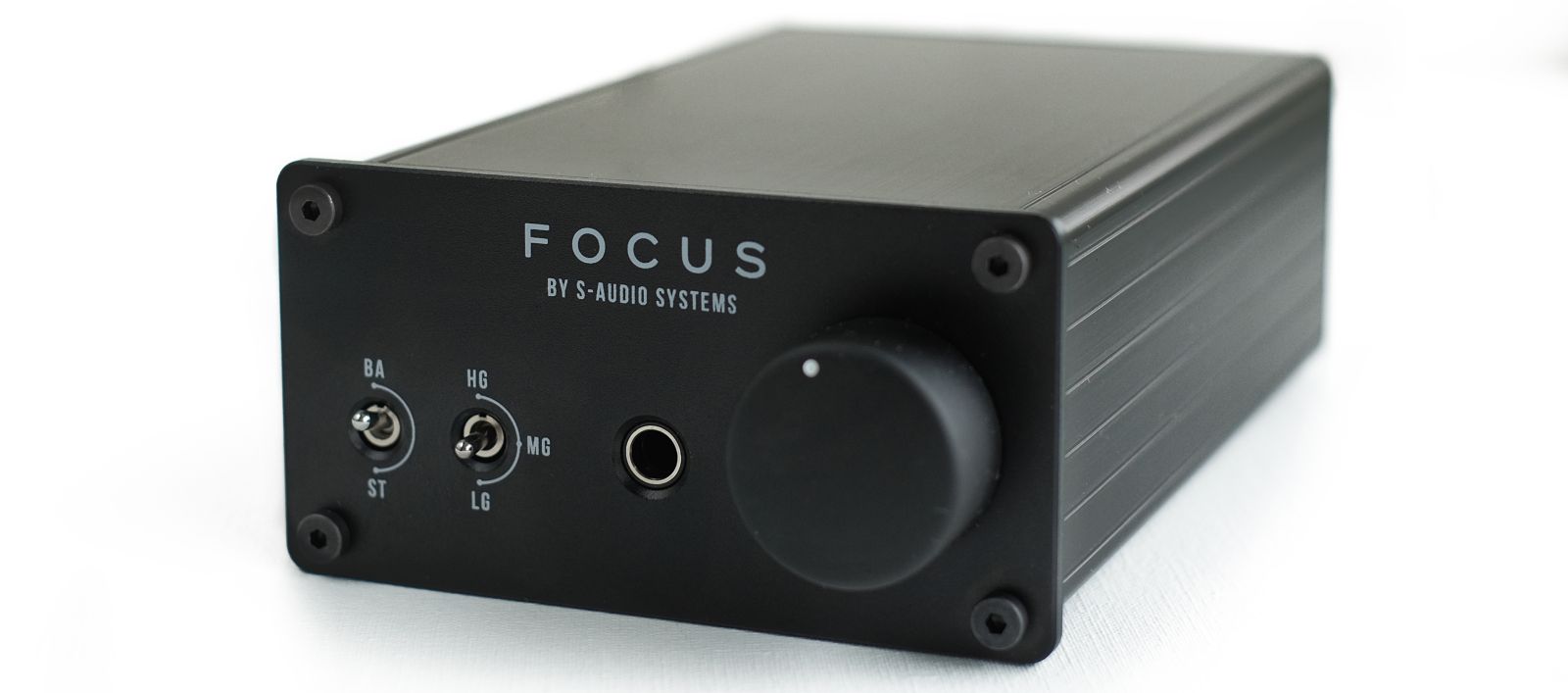
Front panel of the device features (from left to right):
- Mode selection - ST - Stereo or BL - Binaural Audio Processor.
- Gain switch: LG - Low gain / MG - Medium gain / HG - High gain. HG mode is designed to use with planar headphones or with high impedance dynamic headphones, or as a Hi-End DAC. MG mode is for high sensitivity planar headphones or low impedance dynamic headphones. LG mode is for IEMs.
- Output connector - 6.3mm stereo jack
- Volume control knob.
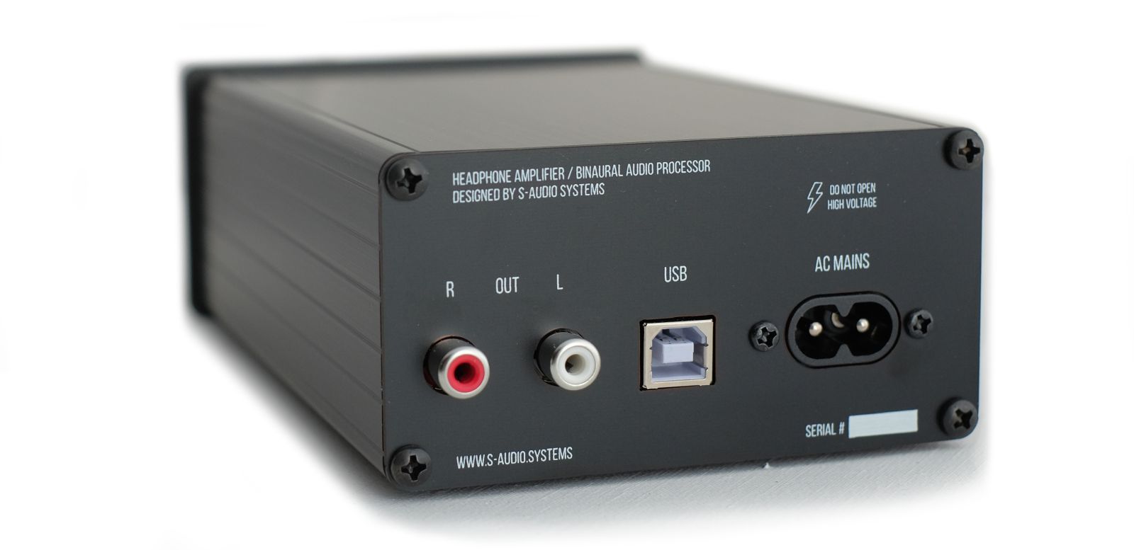
On the back panel of the device (from left to right):
- Line output
- USB input
- AC mains power connector
Any device is just a modulated power supply, so PSU (power supply unit) quality is very important. The power transformer is a low capacitance split bobbin, which minimizes interference from the main power grid and minimizes ground current between devices. Regulators used in the analog part of the DAC are the best on the market today in terms of parameters and positive influence on sound quality series-parallel (“shunt”) stabilizers with low and fixed output impedance, with less than 1μV noise.
Switching on/off of the device from AC mains supply is triggered automatically by the signal from the USB bus (suspend).
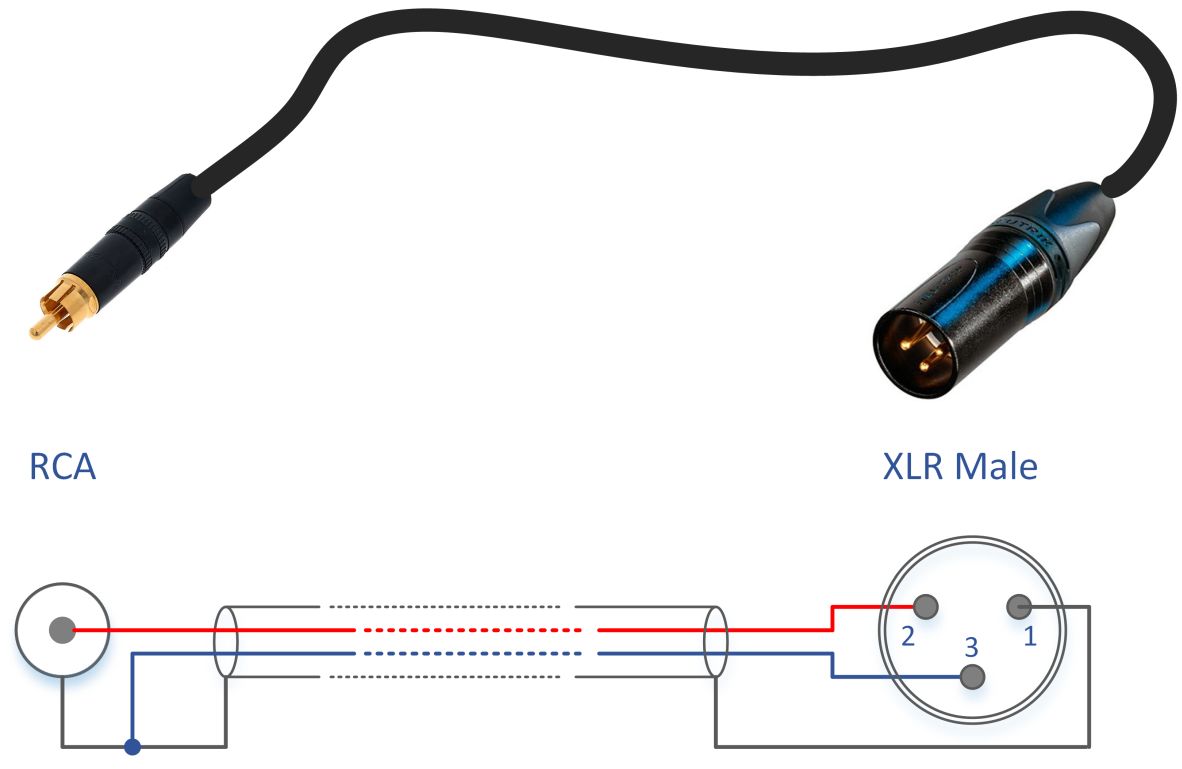
The line output of the device is specifically designed for connecting to the balanced inputs of power amplifiers. Zero output impedance of the line output allows you to get all the advantages of a balanced connection (high CMRR) yet retaining the compatibility with the unbalanced connection of audio devices.
Brief technical data:
- Maximum output current - 400 mA
- Maximum output voltage - 7090 mV RMS
- Output Impedance (HG/MG) – 0 Ohm*
- Output Impedance (LG) – 1.9 Ohm*
- Volume - 0..-50dB
- Gain - 0/-14/-24dB
- Input - USB (PCM 32-192kHz, DSD64-512)
- Output connector - stereo jack 6.3mm
- Power – 230V+-10% 50-60Hz
- Dimensions – 220*110*60 mm
- Power consumption in standard operating mode <1.3W via USB, <20W via 230V mains supply
- Power consumption in standby mode <0.2W via USB, 0W via 230V
*-excluding the resistance of the output connector and the mute relay.
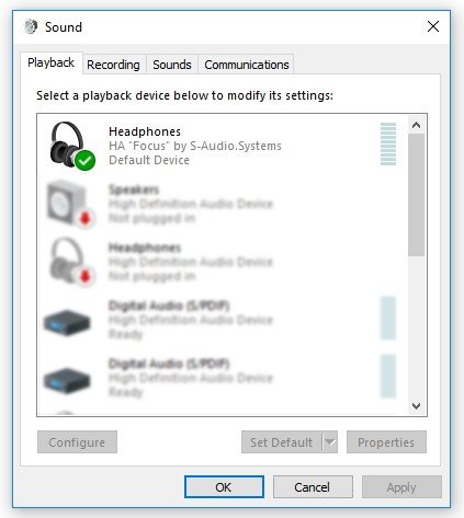
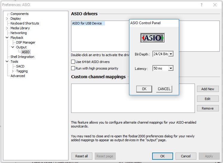
For MacOS, Linux, Android no USB drivers are required. For Windows 7/8/8.1/10 drivers (including ASIO) can be downloaded from download page
.
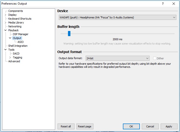
For correct output of audio data under Windows OS use only ASIO (needs to be configured for 24-bit/50ms), Kernel Streaming or WASAPI Exclusive modes.
References:
- Stanley A. Gelfand “Hearing: An Introduction to Psychological and Physiological Acoustics” 5th Edition 2010 Informa UK
- “Loudspeaker and Headphone Handbook” Third Edition Edited by John Borwick with specialist contributors 2001
- J. W. S. Rayleigh “The Theory of Sound” 1894
- B.B.Bauer “Improving headphone listening comfort” Journal of the Audio Engineering Society, Vol.13, No.4, pp 300-302, April 1965.
- B. B. Bauer “Stereophonic to binaural conversion apparatus” USP 3,088,997
- Siegfried Linkwitz “Improved Headphone Listening. Build a stereo-crossfeed circuit” Audio; December 1971
- C. Phillip Brown and Richard O. Duda “A Structural Model for Binaural Sound Synthesis” IEEE TRANSACTIONS ON SPEECH AND AUDIO PROCESSING, VOL. 6, NO. 5, SEPTEMBER 1998
- Toni Liitola “Headphone Sound Externalization” HELSINKI UNIVERSITY OF TECHNOLOGY Mar 7, 2006
- S M A Basha, Abhinav Gupta, Anshul Sharma “Stereo widening system using binaural cues for headphones” Samsung Electronics
- Thomas M.V. “Improving the stereo headphone sound image” JAES №7/8 1977
- Duane H. Cooper, Jerald L. Bauck “Head diffraction compensated stereo system” USP 5,136,651
- Henrik Moller, Dorte Hammershoi, Clemen Boje Jensen, Michael Friis Sorensen “Binaural synthesis, head-related transfer functions, and uses thereof” USP 6,118,875
- Makoto Iwahara, Toshinori Mori “Stereophonic sound reproduction system” USP 4,118,599
- Akitoshi Yamada, Toshiyuki Goto, Yoichi Kimura, Yoshinobu Kikuchi “Out-of-head localization headphone listening device” USP 4,097,689
- Chu Moy “An Acoustic Simulator for Headphone Amplifiers”
- Jan Meier “A diy passive crossfeed filter”
- Jan Meier “A DIY Headphone Amplifier”
- John Conover “Spatial Distortion Reduction Headphone Amplifier”
- Stephen A. Davis, Martin Walsh, David Berners “Dynamic decorrelator for audio signals” USP 6,714,652
- Andrew J. Oxenham “Binaural Hearing” Harvard-MIT Division of Health Sciences and Technology 2005
- Bauer stereophonic-to-binaural DSP
- Naive Crossfeed
- Koenig, Florian M. “The Causals of Headphones Tone Coloration Variations Related on the Human Pinna Influence”
- Toni Kemhagen “The Lindesberg Portable Headphone Amplifier with Crossfeed”
- Grace m902
- Grace m903
- HeadRoom Supreme
- HeadRoom Ultra Desktop Amp
- Headstage Arrow
- SPL Phonitor
- Merlion. Усилитель для наушников с взаимным влиянием каналов
- С. Агеев “Сверхлинейный УМЗЧ с глубокой ООС” Радио №10-12 за 1999 г. и №1,2,4-6,9-11 за 2000 г.
- Sean E. Olive and Todd Welti "The Relationship between Perception and Measurement of Headphone Sound Quality"
- Sean E. Olive, Todd Welti, and Elisabeth McMullin "Listener Preferences for In-Room Loudspeaker and Headphone Target Responses"
- Sean E. Olive, Todd Welti, and Elisabeth McMullin "Listener Preference For Different Headphone Target Response Curves"
- Floyd E. Toole "THE ACOUSTICS AND PSYCHOACOUSTICS OF HEADPHONES"
- Siegfried Linkwitz "A Model for Rendering Stereo Signals in the ITD-Range of Hearing"
- Nobumitsu Asahi, Hiroshi Aoyama, Susumu Matsuoka "HEADPHONE HEARING SYSTEM TO REPRODUCE NATURAL SOUND LOCALIZATION" Trio-Kenwood Corporation
- Erich Meier "Simulation of a Near-Field Loudspeaker System on Headphones"
- John Siau "The Sonic Advantages of Low-Impedance Headphone Amplifiers"
- John Caldwell "Stabilizing difference amplifiers for headphone applications"
- Peter G. Craven "Antialias Filters and System Transient Response at High Sample Rates" J. Audio Eng. Soc., Vol. 52, No. 3, 2004 March
- Peter G. Craven "Controlled pre-response antialias filters for use at 96kHz and 192kHz" J. Audio Eng. Soc., Convention Paper 5822, 2003 March
- Abhijit Kulkarni & H. Steven Colburn "Role of spectral detail in sound-source localization" NATURE | VOL 396 | 24/31 DECEMBER 1998
"Directly or indirectly, all questions connected with this subject must come for decision to the ear, as the organ of hearing; and from it there can be no appeal" J.W.S. Rayleigh